
Contact us
E-mail: info@hktpump.com
Phone: +86-13323110006
WhatsApp: +8613323110006
Yigu Information Industry Park, Xinzhaidian, Zhao County, Shijiazhuang, Hebei Province, China

Submersible Slurry Pump
Share to


- 产品描述
-
Product Introduction and Description
The ZJQ and NSQ submersible slurry pumps and sand suction pumps are hydraulic machines where the motor and pump are coaxial and submerged in the medium. The pump's flow components are made of high-strength wear-resistant alloys, wear-resistant cast iron, and cast steel, etc. The material of the flow components is determined based on the liquid discharged by the customer's operation. The pump has a large flow passage and is suitable for transporting media containing relatively large solid particles such as mud, ore pulp, coal pulp, sand and gravel, etc. It can also be used for suction, spraying, and irrigation of rivers, dredging, manure, and slurry feed, as well as municipal, chemical dyeing, pharmaceutical, shipbuilding, and food industries, and for suction of high-concentration liquids, sewage, and pasty substances, etc. It is an important piece of equipment that cannot be replaced by submersible sewage pumps.
This series of products is designed and manufactured using advanced technologies from home and abroad. In addition to the main impeller, the pump also has a stirring impeller at the bottom, which can spray the accumulated sludge into a turbulent flow, allowing the pump to achieve high-concentration transportation without auxiliary devices. The unique sealing device effectively balances the pressure inside and outside the oil chamber, maximizing the reliability of the mechanical seal. The motor uses various protection measures such as overheating protection and water ingress detection protection, and replaces the usability, reliability, and service life of various vertical pumps. It can operate safely and reliably under harsh working conditions for a long time.
Suitable for pumping construction sand, fine sand, sludge, tailings pulp, ore sand, iron sand ore, rivers, lakes, reservoirs, and ports, etc., for sand dredging and dredging projects. It can also be used for removing sediment in sedimentation tanks of steel mills, power plants, iron ore plants, and oil fields, etc., as well as wastewater treatment plant sediments, etc.
The company is engaged in the research and development and production of hydraulic sand dredging and dredging equipment, and provides experience with corresponding vertical and horizontal dredging sand pumps for different construction environments. It has developed submersible slurry pumps and sand suction pumps. We always adhere to the people-oriented approach and technological innovation, continuously improving internal management, enhancing product quality, providing excellent and unique after-sales service, and building a good corporate reputation to continuously meet customer requirements. Achieving your success with our expertise is our eternal pursuit!
Structural Description
1. The whole machine is a dry pump type, and the motor uses an oil chamber sealing method with an internal mechanical seal to effectively prevent high-pressure water and impurities from entering the motor cavity.
2. In addition to the main impeller, there is also a stirring impeller that can stir the sludge sediment at the bottom of the water into a turbulent flow before extraction.
3. The impellers and stirring impellers and other flow components are made of high-hardness, high-strength wear-resistant alloys (C), cast iron (M), and cast steel (G), with strong sand discharge capacity and the ability to discharge larger solid particles.
4. The motor is submerged underwater, not limited by the suction head, with high sludge suction efficiency and more thorough dredging.
5. The overall equipment is simplified, without the need for auxiliary stirring devices or spraying devices, making operation simple and reducing the total investment of the unit.
6. The stirring impeller is directly close to the sedimentation surface and controls the concentration through the submersion depth. In the case of a high specific gravity of the medium, auxiliary devices can be added to increase the medium concentration.
Operating Conditions
1. The power supply is a 50HZ/60HZ/380V/415V/660V/1140V three-phase AC power supply, and the capacity of the distribution transformer is 2-3 times the rated capacity of the motor.
2. The medium temperature must not exceed 60°C, xSQ(R) type not exceeding 140°C, and does not contain flammable or explosive gases.
3. Maximum weight concentration of solid particles in the medium: ash slag is 45%, and slag is 60%.
4. In pumps with an internal self-circulating cooling system, the motor part is exposed to the liquid surface no more than 1/2.
5. Submersion depth of the unit: no more than 40 meters, the minimum submersion depth is based on submerging the motor.
6. The working position of the unit in the medium is vertical, and the upper part is suspended for positioning.
7. Under normal circumstances, the pump must be used within the operating head range to ensure that the motor does not overload. If it needs to be used in the full head range, please specify it when ordering so that the manufacturer can produce it accordingly.
Advantages
(A) Compared with ordinary horizontal pumps, submersible slurry pumps and sand suction pumps have the following advantages:
1. Compact structure and small footprint. Since it works submerged in the liquid, it can be directly installed in the sewage sand discharge pool without the need to build a special pump room to install the pump and motor, saving a lot of land and construction costs.
2. Convenient installation and maintenance, free installation.
3. Long continuous running time. Because the pump and motor are coaxial and the shaft is short, the rotating parts are light, so the load (radial) on the bearings is relatively small, and the service life is much longer than that of ordinary pumps.
4. There are no cavitation damage and priming problems. The latter point in particular brings great convenience to operators. Due to the above advantages, it has been increasingly valued and its scope of use has been expanding, from the original simple transportation of high-concentration sand to now transporting various domestic sewage, industrial wastewater, construction site drainage, liquid feed, etc. It plays a very important role in municipal engineering, industry, hospitals, construction, hotels, water conservancy construction, and various industries.
(B) Sealing Technology
So-called auxiliary impeller hydrodynamic sealing refers to the installation of an auxiliary impeller behind the pump cover that rotates in the opposite direction to the main impeller. When the pump is operating, the auxiliary impeller rotates with the main pump shaft, and the liquid in the auxiliary impeller also rotates. The rotating liquid generates an outward centrifugal force, which, on the one hand, presses against the liquid flowing towards the mechanical seal, reducing the pressure at the mechanical seal. On the other hand, it prevents solid particles in the medium from entering the friction of the mechanical seal, reducing the wear of the mechanical seal block and extending its service life. In addition to its sealing function, the auxiliary impeller can also reduce axial force. In this type of pump, the axial force is mainly composed of the pressure difference force of the liquid acting on the impeller and the gravity of the entire rotating part. The directions of these two forces are the same, and the resultant force is the sum of the two forces. It can be seen that, under the same performance parameters, the axial force of this type of pump is greater than that of a general horizontal pump, and the balancing difficulty is greater than that of a vertical pump. Therefore, in this type of pump, the bearings are prone to damage, and the reason is also largely related to the axial force. If an auxiliary impeller is installed, the direction of the pressure difference force on the auxiliary impeller is opposite to the resultant force of the above two forces, which can offset part of the axial force and thus extend the service life of the bearings. However, there is also a disadvantage to using an auxiliary impeller sealing system: it consumes a certain amount of energy on the auxiliary impeller, generally about 3%. As long as the medium is reasonably designed, this loss can be minimized.
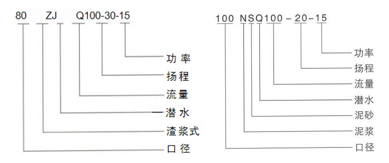
Model Significance
Product Structure Description
ZJQ and NSQ submersible slurry pumps/sand pumps consist of a motor and a pump, separated by an oil isolation chamber and a mechanical seal assembly. They are electromechanical integrated products, with the motor and pump sharing the same shaft (rotor). The entire water pump is short in length and compact in structure. Equipped with multiple protective devices, ensuring safe and reliable pump operation.
Uses Y-series national standard motors with F-class insulation for safe and reliable operation.
Uses double-channel tandem seals with new alloy materials, featuring reliable sealing, wear resistance, and long life.
Flow components use high-chromium slurry pumps, with wear-resistant materials, good performance, and excellent flow performance. The service life is 2-10 times that of similar domestic pumps.
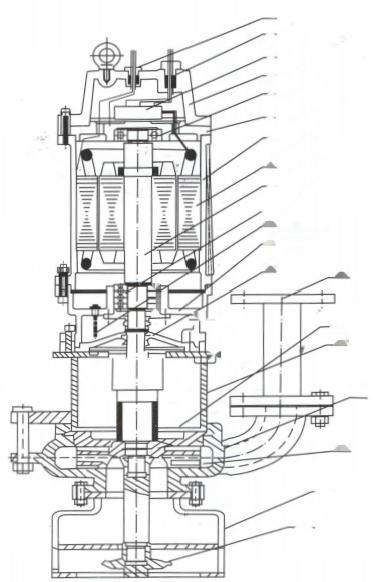
1. Signal Line 11. Oil-Water Probe 2. Motor Wiring 12. Oil Chamber 3. Junction Box 13. Mechanical Seal 4. Motor Cover 14. Guard Plate 5. Bearing 15. Discharge Pipe 6. Upper Shaft Seat 16. Bracket 7. Motor Housing 17. Pump Body 8. Stator 18. Impeller 9. Shaft (Rotor) 19. Base Filter 10. Bearing 20. Cutter Performance Parameters Table
Product Model Speed
(r/min)Flow Rate
(m³/h)Head
(m)Power
(KW)Diameter
(mm)40ZJQ/NSQ 8-12-2.2 1450 8 12 2.2 40 10-21-5.5 10 21 5.5 40 15-12-3 15 12 3 40 18-19-5.5 18 19 5.5 40 23-10-3 23 10 3 40 25-17-5.5 25 17 5.5 40 50NsQ 12-6-3 1450 12 6 3 50 20-20-4 20 20 4 50 25-15-4 25 15 4 50 25-30-7.5 25 30 7.5 50 30-16-5.5 30 16 5.5 50 35-6-4 35 6 4 50 45-14-5.5 45 14 5.5 50 65ZJQ/NSQ 25-15-4 1450 25 15 4 65 47-34-11 47 34 11 65 56-27-11 56 27 11 65 71-25-11 71 25 11 65 80ZJQ/NSQ 10-15-5.5 1450 10 15 5.5 80 30-30-7.5 30 30 7.5 80 45-15-5.5 45 15 5.5 80 70-20-7.5 70 20 7.5 80 Product Model Speed
(r/min)Flow Rate
(m³/h)Head
(m)Power
(KW)Diameter
(mm)80ZJQ/NSQ 70-35-15 1450 70 35 15 80 80-15-7.5 80 15 7.5 80 80-20-11 80 20 11 80 80-45-22 80 45 22 80 100-20-11 100 20 11 80 100-30-15 100 30 15 80 130-19-22 130 19 22 80 100NsQ 80-25-15 1450 80 25 15 100 100-12-7.5 100 12 7.5 100 100-20-15 100 20 15 100 100-30-18.5 100 30 18.5 100 120-18-15 120 18 15 100 120-35-22 120 35 22 100 150-25-22 150 25 22 100 150-38-30 150 38 30 100 160-80-90 160 80 90 100 180-22-22 180 22 22 100 200-35-37 200 35 37 100 150 NS 120-16-15 1450 120 16 15 150 150-22-18.5 150 22 18.5 150 150-35-22 150 35 22 150 Product Model Speed
(r/min)Flow rate
(m³/h)Head
(m)Power
(KW)Diameter
(mm)150 NSQ 180-25-22 1450 180 25 22 150 200-22-22 200 22 22 150 200-35-37 200 35 37 150 200-80-110 200 80 110 150 250-16-22 250 16 22 150 250-22-30 250 22 30 150 250-40-45 250 40 45 150 260-35-45 260 35 45 150 260-60-110 260 60 110 150 280-33-45 280 33 45 150 300-22-30 300 22 30 150 300-30-37 300 30 37 150 300-30-45 300 30 45 150 350-25-37 350 25 37 150 400-30-55 400 30 55 150 450-25-75 450 25 75 150 200 NsQ 300-25-37 1450 300 25 37 200 450-25-55 450 25 55 200 500-35-90 500 35 90 200 Features
1. Adopts advanced technology, has strong sludge discharge capacity, no blockage, and can effectively pass solid particles with a diameter of φ30~φ60 mm.
2. The tearing mechanism can tear and cut fibrous materials, and then discharge them smoothly, without the need to add a filter screen to the pump.
3. Reasonable design, small matching motor power, significant energy saving effect.
4. Uses the latest material mechanical seal, which can ensure the pump runs safely and continuously.
5. Compact structure, easy to move, simple installation, can reduce the cost of engineering, no need to build a pump room.
6. It can be used in the full head range while ensuring that the motor is not overloaded.Installation System Instructions
1. Automatic Coupling Device System
Suitable for long-term fixed use, with the advantages of quick installation, convenient inspection and maintenance. This system uses a special base, fixed at the bottom of the sewage pit, connected to the outlet pipe, the matching support block is installed on the pool top, and the guide rod connects the two, the water pump is connected to the specific bracket, and goes down to the bottom along the guide rod, automatically coupling and sealing with it, while lifting automatically falls off.
2. Mobile Installation System
It is supported by a bracket, and can be operated by connecting the outlet hose. This method is mainly used for emergency or repair work.
Pump Usage and Precautions
1. Before using the pump, carefully check whether the cable is damaged, whether the fasteners are loose or fall off, and whether the pump is deformed or damaged during transportation, storage, and installation.
2. Use a 500V megohmmeter to measure the insulation resistance between the electric pump motor and the ground. The value should not be less than 2 megohms. Otherwise, the stator winding of the motor should be dried. The drying temperature should not exceed 120℃.
3. The installation of this series of pumps has two types: fixed and mobile. When using the fixed automatic installation, the chain should be put into the two hoisting ring screws or lifting plates (deviating from the pump outlet, the connecting line should be parallel to the pump outlet) to lift the electric pump up and down. Slide uniformly and slowly along the guide rail until it is automatically coupled. When using mobile installation, first put on the hose, lift the electric pump up and down with the chain, and pay attention to not using the cable as a rope to avoid danger.
4. After the pump is turned on, the direction of rotation is counterclockwise when viewed from the inlet. If the electric pump reverses, just change the connection position of any two wires in the cable.
5. The ground wire of the electric pump casing must be strictly connected according to the relevant regulations. To ensure personal safety during use, it is strictly forbidden to install people in the water or move around the electric pump during operation, to prevent electric shock accidents due to electric pump leakage.
6. The electric pump must be equipped with a fully automatic water pump control cabinet under normal circumstances. Do not directly connect to the power grid or use a knife switch to turn on the power to ensure the normal operation of the electric pump.
7. Do not run the electric pump in a low head condition for a long time (the general head should not be lower than 60% of the rated head), and it is best to control it within the recommended head range to prevent the electric pump from overloading and burning out the motor.
8. Pumps without self-circulating cooling device are strictly prohibited from running with the whole body exposed to the water for a long time, to prevent the electric pump from overheating and damage.
Maintenance
1. The electric pump should be managed and used by a dedicated person, and regularly check whether the insulation resistance between the electric pump winding and the casing is normal.
2. After each use, especially when used for thicker and more viscous slurry, the electric pump should be placed in clean water and operated for several minutes to prevent sediment from remaining in the pump, ensuring the cleanliness of the electric pump.
3. If the electric pump is not used for a long time, it should be removed from the water and should not be soaked in the water for a long time to reduce the chance of the motor stator winding getting damp, and increase the service life of the electric pump.
4. Under normal conditions, the pump should be refilled or replaced with oil in the oil chamber (10~30# engine oil) after every 300~500 hours of use, so that the mechanical seal maintains a good lubrication state, and improves the service life of the mechanical seal.
5. After the electric pump is disassembled and repaired, the casing assembly must be checked by a 0.2MPa airtight test to ensure reliable motor sealing.
6. The sealing ring between the impeller and the pump body has a sealing function. If the seal is damaged, it will directly affect the pump's performance. It should be replaced if necessary.
Common Malfunctions and Troubleshooting Methods
Malfunction Cause Troubleshooting Method Insufficient flow
or no water discharge1. Motor reversal
2. Impeller flow passage or pipeline blockage
3. System head is too high, or the selected pump's head is significantly lower than the actual requirement
4. Severe impeller wear
5. Liquid level too low, causing the pump to suck in air
6. Check valve installed in reverse direction1. Correct motor rotation
2. Clear debris from the impeller or pipeline. It is best to install a filter screen around the pump (but do not install a filter screen at the pump inlet).
3. Try to reduce the system head (e.g., use larger diameter or smoother pipes, reduce the number of bends, or increase the radius of curvature of the bends) or use a pump with a higher head.
4. Replace the impeller
5. Adjust the float switch position so that the minimum liquid level meets the installation requirements.
6. Correct the check valve direction.Cannot start 1. Phase loss
2. Impeller jammed
3. Winding connection or cable break
4. Stator winding burned out
5. Control electrical malfunction
6. Power voltage too low1. Check the wiring and eliminate phase loss issues
2. Clear debris. It is best to install a filter screen around the pump (but do not install a filter screen at the pump inlet).
3. Check with an ohmmeter and repair
4. Repair and replace the winding or stator
5. Check the control cabinet and repair or replace electrical components
6. Address the power voltage issueStator burned out 1. Without protective control electrical appliances; operation or startup under phase loss conditions; impeller jammed or detached; excessive medium concentration; clogged cooling system
2. Motor water ingress due to seal damage
3. Motor water ingress due to loose fasteners
4. Motor running above water level for an extended timeBefore using the motor after repair, you must:
1. Configure protective control electrical appliances and: Check the wiring and clear phase loss faults; clear debris, tighten impeller fastening screws and stainless steel spring washers; dilute the medium with water; flush and clear the cooling system
2. Replace the mechanical seal or "O" ring
3. Tighten all fasteners
4. Ensure that the minimum liquid level does not fall below that specified in the installation drawingExcessive current 1. Higher density or viscosity of the pumped liquid
2. The selected pump's head significantly exceeds the actual requirement, or operating conditions have changed, causing a significant reduction in the system head, causing the pump to operate beyond the recommended flow rate
3. Bearing damage
4. Debris trapped between impeller and pump body (e.g., at the mouth ring)
5. Power voltage too low1. Change the density or viscosity of the pumped liquid
2. Close the outlet valve, reduce the flow rate, trim the impeller, or replace a lower head pump
3. Replace the bearings
4. Clear debris
5. Address the power voltage issueHigh vibration and noise 1. The selected pump's head significantly exceeds the actual requirement, or operating conditions have changed, causing a significant reduction in the system head, causing the pump to operate beyond the recommended flow rate
2. Liquid level too low, causing the pump to suck in air
3. Improper piping arrangement, such as a valve installed close to the pump outlet and the valve is slightly closed. A bend is installed close to the pump outlet. The diameter of the discharge pipe close to the pump outlet suddenly decreases. The diameter of the suction pipe of the installed pump is smaller than the inlet diameter of the suction bend.
4. Bearing is lacking grease or damaged
5. Debris is stuck between the impeller and the pump body (accompanied by increased current)1. Close the outlet valve, reduce the flow, trim the impeller, or replace a pump with a lower head
2. Adjust the float switch position so that the lowest liquid level meets the requirements of the installation drawing
3. Find out the specific problems with the pipeline settings and solve them accordingly
4. Lubricate or replace the bearings
5. Remove debris
Product System
The company's industrial pump production base focuses on meeting the needs of various industrial scenarios. We are committed to creating products such as slurry pumps, desulfurization pumps, dredging pumps, submersible pumps, and chemical pumps. From the demand for high wear-resistant slurry pumps in large-scale mining, to the dependence on high-efficiency desulfurization pumps in power plant desulfurization, to the strict requirements for high corrosion-resistant chemical pumps in fine chemical processes, we can provide high-performance products that are suitable for all. These pumps are widely used in industries such as mining, power plant desulfurization, river sand mining, metallurgy and steel, chemical industry, etc.
The valve production base covers various categories such as ball valves, gate valves, butterfly valves, etc. With excellent quality and reliable performance, it is widely used in the fields of oil and gas transmission pipelines, urban water supply and drainage systems, etc., to ensure the safe and stable operation of various fluid transmission systems.
Contact Us
Keywords:
Related Products


Your One Stop, One Solution!
Each optimal solution is determined by its particular application requirements, design, and installation parameters combined with our experience and know-how on pump technology.
CONTACT US
E-Mail: info@hktpump.com
Tel.:+86-13323110006
WhatsApp:+86-13323110006
Add.:Yigu Information Industry Park, Xinzhaidian, Zhao County, Shijiazhuang, Hebei Province, China